The most important responsibilities of the NSS are call establishment, call control and routing of calls between different fixed and mobile switching centers and other networks. Other networks are, for example, the national fixed-line network, which is also called the Public Switched Telephone Network (PSTN), international fixed-line networks, other national and international mobile networks and Voice over Internet Protocol (VoIP) networks. Furthermore, the NSS is responsible for subscriber management.

The Mobile Switching Center (MSC)
- The MSC is the central element of a mobile telecommunication network, which is also called a Public Land Mobile Network (PLMN) in the standards.
- In a classic circuit-switched network, all connections between subscribers are managed by the MSC and are always routed over the switching matrix even if two subscribers that have established a connection communicate over the same radio cell.
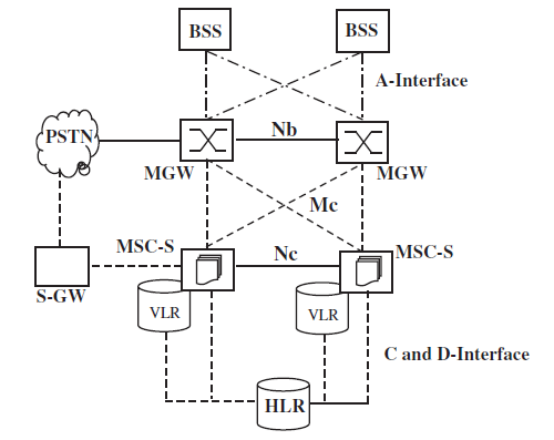
- In a virtual circuit-switched network, the MSC is split into two parts: the MSC Server (MSC-S) and the MG. The IP-based MG replaces the switching matrix while the MSC-S contains the same logic for subscriber management and call control as the central processing unit (CPU) of a classic MSC.
The management activities to establish and maintain a connection are part of the Call Control (CC) Protocol, which is generally responsible for the following tasks:
- Registration of mobile subscribers: When the mobile device, also referred to as mobile station (MS), is switched on, it registers to the network and is then reachable by all other subscribers of the network.
- Call establishment and call routing between two subscribers.
- Forwarding of SMS (short messaging service) messages.
As subscribers can roam freely in the network, the MSC is also responsible for the Mobility Management (MM) of subscribers. This activity comprises the following tasks:
- Authentication of subscribers at connection establishment
- If no active connection exists between the network and the mobile device, the MSC has to report a change of location to the network to be reachable for incoming calls and SMS messages. This procedure is called location update.
- If the subscriber changes its location while a connection is established with the network, the MSC is part of the process that ensures that the connection is not interrupted and is rerouted to the next cell. This procedure is called handover.
To enable the MSC to communicate with other nodes of the network, it is connected to them via standardized interfaces as shown in the Figures above. This allows network operators to acquire different components for the network from different network equipment vendors.
- These interfaces are either transmitted over time slots in circuit-switched E-1 lines or over an IP-based network. Only the lower protocol layers are affected by this. On the application layer, both variants are identical.
- The BSS, which connects all subscribers to the core network, is connected to the MSCs via a number of 2-Mbit/s E-1 connections. This interface is called the A-interface. The BSSMAP and DTAP protocols are used over the A-interface for communication between the MSC, the BSS and the mobile devices.
- As an E-1 connection can only carry 31 channels, many E-1 connections are necessary to connect an MSC to the BSS. In practice, this means that many E-1s are bundled and sent over optical connections such as STM-1 to the BSS.
- As an MSC only has a limited switching capacity and processing power, a PLMN is usually composed of dozens of independent MSCs. Each MSC thus covers only a certain area of the network. To ensure connectivity beyond the immediate coverage area of an MSC, E-1s, which are again bundled into optical connections, are used to interconnect the different MSCs of a network.
- As a subscriber can roam into the area that is controlled by a different MSC while a connection is active, it is necessary to change the route of an active connection to the new MSC (handover). The necessary signaling connection is called the E-interface. ISUP is used for the establishment of the speech path between different MSCs and the MAP protocol is used for the handover signaling between the MSCs.
- The C-interface is used to connect the MSCs of a network with the HLR of the mobile network. While the A-and E-interfaces that were described previously always consist of signaling and speech path links, the C-interface is a pure signaling link. Speech channels are not necessary for the C-interface as the HLR is a pure database that cannot accept or forward calls. Despite being only a signaling interface, E-1 connections are used for this interface. All timeslots are used for signaling purposes or are unused.
a voice connection is carried over a 64 kbit/s E-1 timeslot in a classic circuit-switched fixed-line or mobile network. Before the voice signal can be forwarded, it needs to be digitized. For an analog fixed-line connection, this is done in the switching center, while an ISDN fixed-line phone or a GSM mobile phone digitizes the voice signal by itself.
An analog voice signal is digitized in three steps :
- the bandwidth of the input signal is limited to 300–3400 Hz to be able to carry the signal with the limited bandwidth of a 64- kbit/s timeslot.
- The signal is sampled at a rate of 8000 times per second.
- The next processing step is the quantization of the samples, which means that the analog samples are converted into 8-bit digital values that can each have a value from 0 to 255.

MSC Server and Media Gateway
In most of today’s mobile voice networks, circuit-switched components have been replaced with IP-based devices. The MSC has been split into an MSC-Server (MSC-S) and an MGW.
- The MSC-Ss are responsible for CC and MM (signaling), and the MGWs handle the transmission of virtual voice circuits (user data).
- To establish a voice connection, MSC-Ss and MGWs communicate over the Mc-interface on which the H.248/MEGACO (Media Gateway Control) protocol is used. This interface does not exist in the classical model, as the MSC contained both components.
- To add redundancy and for load balancing reasons, several MSC-Ss and MGWs can be interconnected in a mesh. If an MSC-S fails, an MGW can thus still continue to operate and is then controlled by another server. Thus, a single MSC-S is no longer solely responsible for a single geographical area as was the case in the traditional model.
- On the radio network side, the A-interface continues to be used to connect the radio network to the MSC-Ss and MGWs. But it has been made more flexible and can now be connected to several media gateways. This adds redundancy toward the radio network as well, as a geographical region can still be served even if a media gateway fails.
- The Nc-interface is used to transport voice calls within the core network, for example, to gateways, to other mobiles or fixed networks. The protocol used on this interface is referred to as the BICC protocol and is very similar to the traditional ISUP protocol.
- By using an SGW (signaling gateway) as shown in the Figure, the protocol can be converted into ISUP to be able to forward calls to other core networks that are still based on the classic model.
- Virtual speech channels that have been negotiated over the Nc-interface are transmitted between MGWs over the Nb-interface. The combination of the Nb-interface and Nc-interface thus replaces the E-interface of the classic network architecture.
- A voice channel is transmitted over IP connections either as PCM/G.711, Narrowband-AMR or Wideband-AMR, depending on the type of radio network, configuration of the network and the capabilities of the mobile device.
- At the borders of the core network, for example, to and from the A-interface to the GSM radio network or to and from a classic fixed-line PSTN network, MGWs can convert media streams, for example, between Narrowband-AMR over IP to G.711/PCM over E-1.
- This requires, however, that an MGW contains both Ethernet ports and E-1 ports. Gateways between mobile networks are usually still based on ISUP and circuit-switched links, even though most networks are based on IP technology today.
- In the future, this is expected to change as advanced speech codecs such as Wideband-AMR can only be used over BICN and IP-based transport links. Like in classic core networks, the C- and D-interfaces are used in a BICN network to communicate with the HLR. Instead of E-1 links, however, communication is based on IP links today.
The Visitor Location Register (VLR)
Each MSC has an associated Visitor Location Register (VLR), which holds the record of each subscriber that is currently served by the MSC. These records are only copies of the original records, which are stored in the HLR.
The VLR is mainly used to reduce the signaling between the MSC and the HLR. If a subscriber roams into the area of an MSC, the data are copied to the VLR of the MSC and are thus locally available for every connection establishment.
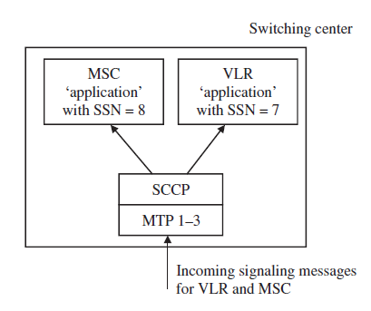
While the standards allow implementation of the VLR as an independent hardware component, all vendors have implemented the VLR simply as a software component in the MSC. This is possible because MSC and VLR use different SCCP SSNs as shown in the Figure and can thus run on a single physical node.
When a subscriber leaves the coverage area of an MSC, his record is copied from the HLR to the VLR of the new MSC, and is then removed from the VLR of the previous MSC.
The Home Location Register (HLR)
The HLR is the subscriber database of a GSM network. It contains a record for each subscriber, which contains information about the individually available services.
The International Mobile Subscriber Identity (IMSI) is an internationally unique number that identifies a subscriber and is used for most subscriber-related signaling in the network. It is stored in the subscriber’s subscriber identity module (SIM) card and in the HLR and is thus the key to all information about the subscriber.

The IMSI consists of the following parts:
- The Mobile Country Code (MCC), identifies the subscriber’s home country.
- The Mobile Network Code (MNC), This is the national part of a subscriber’s home network identification. A national identification is necessary because there are usually several independent mobile networks in a single country.
- The Mobile Subscriber Identification Number (MSIN). The remaining digits of the IMSI form the MSIN, which uniquely identifies a subscriber within the home network.
As an IMSI is internationally unique, it enables a subscriber to use his phone abroad if a GSM network is available that has a roaming agreement with his home operator.
- When the mobile device is switched on, the IMSI is retrieved from the SIM card and sent to the MSC.
- There, the MCC and MNC of the IMSI are analyzed and the MSC is able to request the subscriber’s record from the HLR of the subscriber’s home network.
The phone number of the user, which is called the Mobile Subscriber Integrated Services Digital Network Number (MSISDN) in the GSM standards, has a length of up to 15 digits and consists of the following parts:
- The country code is the international code of the subscriber’s home country.
- The NDC usually represents the code with which the network operator can be reached.
- The remainder of the MSISDN is the subscriber number, which is unique in the network.
There is usually a 1:1 or 1:N relationship in the HLR between the IMSI and the MSISDN. Furthermore, a mobile subscriber is normally assigned only a single MSISDN. However, as the IMSI is the unique identifier of a subscriber in the mobile network, it is also possible to assign several numbers to a single subscriber.
Another advantage of using the IMSI as the key to all subscriber information instead of the MSISDN is that the phone number of the subscriber can be changed without replacing the user’s SIM card or changing any information on it.
To change the MSISDN, only the HLR record of the subscriber needs to be changed. In effect, this means that the mobile device is not aware of its own phone number. This is not necessary because the MSC automatically adds the user’s MSISDN to the message flow for a mobile-originated call establishment so that it can be presented to the called party.
Many countries have introduced a functionality called mobile number portability (MNP), which allows a subscriber to retain his MSISDN even if he wants to change his mobile network operator. This is a great advantage for subscribers and for the competition between mobile operators, but it also implies that it is no longer possible to discern the mobile network to which the call will be routed from the NDC (the networks have to query a MNP database for every call to a mobile subscriber to find out if the call can be routed inside the network or if it has to be forwarded to a different national mobile network).
Apart from the IMSI and MSISDN, the HLR contains a variety of information about each subscriber, such as which services he is allowed to use.

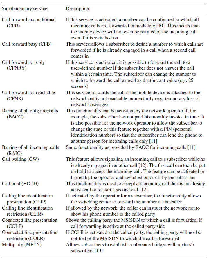
- Most services can be configured by the subscriber via a menu on the mobile device. The menu, however, is just a graphical front end for the user and the mobile device translates the user’s commands into numerical strings which start with a ‘*’ character. These strings are then sent to the network by using an Unstructured Supplementary Service Data (USSD) message.The codes are standardized and are thus identical in all networks.
- As the menu is only a front end for the USSD service, the user can also input the USSD strings himself via the keypad. After pressing the ‘send’ button, which is usually the button that is also used to start a phone call after typing in a phone number, the mobile device sends the string to the HLR via the MSC, where the string is analyzed and the requested operation is performed.
The Authentication Center (AuC)
Another important part of the HLR is the AuC.
The AuC contains an individual key per subscriber (Ki), which is a copy of the Ki on the SIM card of the subscriber. As the Ki is secret, it is stored in the AuC and especially on the SIM card in a way that prevents it from being read directly.
For many operations in the network, for instance, during the establishment of a call, the subscriber is identified by using this key. Thus, it can be ensured that the subscriber’s identity is not misused by a third party.
- The authentication process is initiated when a subscriber establishes a signaling connection with the network before the actual request (e.g. call establishment request) is sent.
- The MSC requests an authentication triplet from the HLR/AuC.
- The AuC retrieves the Ki of the subscriber and the authentication algorithm (A3 algorithm) based on the IMSI of the subscriber that is part of the message from the MSC.

The Ki is then used together with the A3 algorithm and a random number to generate the authentication triplet, which contains the following values:
- RAND: A 128-bit random number.
- SRES: The signed response, (SRES), is generated by using Ki, RAND and the authentication A3 algorithm, and has a length of 32 bits.
- Kc: The ciphering key, Kc, is also generated by using Ki and RAND. It is used for the ciphering of the connection once the authentication has been performed successfully.
- RAND, SRES and Kc are then returned to the MSC, which then performs the authentication of the subscriber.
It is important to note that the secret Ki key never leaves the AuC.
To speed up subsequent connection establishments, the AuC usually returns several authentication triplets per request. These are buffered by the MSC/VLR and are used during the subsequent connection establishments.
- In the next step, the MSC sends the RAND inside an authentication request message to the mobile device.
- The mobile device forwards the RAND to the SIM card, which then uses the Ki and the authentication A3 algorithm to generate a signed response (SRES*).
- The SRES* is returned to the mobile device and then sent back to the MSC inside an authentication response message.
- The MSC then compares SRES and SRES*, and if they are equal, the subscriber is authenticated and allowed to proceed with the communication.

As the secret key, Ki, is not transmitted over any interface that could be eavesdropped on, it is not possible for a third party to correctly calculate a SRES. As a fresh random number is used for the next authentication, it is also pointless to intercept the SRES* and use it for another authentication.
The Short Messaging Service Center (SMSC)
- The Short Messaging Service Center is used to store and forward short messages.
- The sender sends the SMS via a signaling channel to the MSC as shown in the Figure.
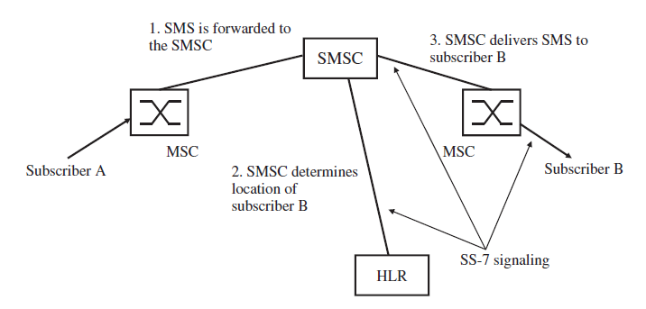
- As a signaling channel is used, an SMS is just an ordinary DTAP SS-7 message and thus, apart from the content, very similar to other DTAP messages, such as a location update message or a setup message to establish a voice call.
- Apart from the text, the SMS message also contains the MSISDN of the destination party and the address of the SMSC, which the mobile device has retrieved from the SIM card.
- When the MSC receives an SMS from a subscriber, it transparently forwards the SMS to the SMSC. As the message from the mobile device contains the address of the subscriber’s SMSC, international roaming is possible and the foreign MSC can forward the SMS to the home SMSC without the need for an international SMSC database.
- To deliver a message, the SMSC analyzes the MSISDN of the recipient and retrieves its current location (the MSC concerned) from the HLR.
- The SMS is then forwarded to the MSC concerned. If the subscriber is currently attached, the MSC tries to contact the mobile device, and if an answer is received, the SMS is forwarded.
- Once the mobile device has confirmed the proper reception of the SMS, the MSC notifies the SMSC as well and the SMS is deleted from the SMSC’s data storage.
- If the subscriber is not reachable because the battery of the mobile device is empty, the network coverage has been lost temporarily, or if the device is simply switched off, it is not possible to deliver the SMS. In this case, the message waiting flag is set in the VLR and the SMS is stored in the SMSC. Once the subscriber communicates with the MSC, the MSC notifies the SMSC to reattempt delivery.
- As the message waiting flag is also set in the HLR, the SMS also reaches a subscriber that has switched off the mobile device in London, for example, and switches it on again after a flight to Los Angeles. When the mobile device is switched on in Los Angeles, the visited MSC reports the location to the subscriber’s home HLR (location update). The HLR then sends a copy of the user’s subscription information to the MSC/VLR in Los Angeles including the message waiting flag and thus the SMSC can also be notified that the user is reachable again.
- The SMS delivery mechanism does not include a delivery report for the sender of the SMS by default. The sender is only notified that the SMS has been correctly received by the SMSC. However, if supported by a device, it is also possible to request an end-to-end delivery notification from the SMSC.
- In practice, there are a number of different ways this is implemented in mobile devices. In some mobile operating systems, delivery reports can be activated in the SMS settings. Confirmations are then shown with a symbol next to the message or are displayed in the status bar. Other operating systems include a separate list of received or pending confirmations.
